
The low melting point of aluminium makes it possible to use a permanent steel mould for castings. An injection plunger pushes liquid aluminium into the mould cavity and compresses the part during solidification in die casting. During solidification, the liquid metal typically reaches speeds of up to 60 meters per second, with pressures reaching 800 bar. The clamping force employed by the moulding press to hold the cavity closed and the pressure provided by the plunger to contain the pressure exerted on the part are defined by the size of the cavity and the pressure supplied by the plunger to hold the pressure exerted on the part. Most miniature presses have a capacity of 1000 kN, and the most extensive, 35000 kN (3500 T). Therefore, the force of the press is directly related to the projected surface of the moulded part.
The die-casting process is divided into 6 phases: liquid metal transfer, injection approach phase, rapid injection, intensification, ejection and mould lubrication. Each stage is optimized to maximize the production rate and minimize the number of rejected parts.
There are three variants of this process:
– Traditional die casting
– Vacuum die casting, including vacuum casting for structural applications
– Semi-solid die casting, which is much less common.
The main advantage of this process is the fast production rate, which lowers production costs and approaches mass markets such as automotive. The metal mould’s quick cooling results in an excellent metallurgical structure on the skin’s surface, contributing to good mechanical qualities. The surface polish is outstanding, as are the dimensional tolerances. The design freedom, on the other hand, is limited to the mould opening axis. The process is low labour-intensive but has high capital and tooling cost. For a large production run of more than 10,000 parts, the die-casting process offers the lowest production cost per part among the foundry processes.
The main disadvantage of the traditional process (where no vacuum is applied in the cavity) is porosity in the centre of the die-cast parts due to air trapped during the injection. When the part is heated, the entrapped air causes blisters to form. These blisters are created by the gas trapped in part expanding, making it impossible to execute typical solution heat treatments to achieve optimal mechanical qualities; this phenomenon also makes welding and the application of some baked paints difficult. Because the casting skin offers mechanical strength, many classic die castings can still be effectively cast, accounting for more than half of all aluminium castings produced.
In conventional die casting, secondary alloys (recycled) with a high alloying element content (iron and zinc) are often used, which gives good mechanical strength despite an elongation of less than 3%. Heat treatment is used to improve the mechanical strength of die-cast alloys while preventing blisters.
Using a vacuum in the cavity to reduce trapped air and real-time management of the casting cycle results in exceptional component quality. Maximum elongation at break is achieved by combining a high vacuum pressure method (50 bar) with low iron primary alloy formation. It allows parts used in structural applications to be heat treated. The desire to lower the weight of land vehicles is driving these innovations, and vacuum die casting is the appropriate choice for a high-speed casting technique for structural aluminium castings. The most active area in the foundry field is the development of this method and dedicated alloys.
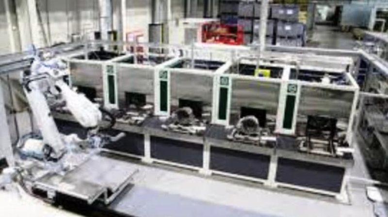
Elements of a mould and the production cell
The die-casting process has two principles of feeding the liquid metal: hot chamber technology and cold chamber technology. The hot chamber process uses a plunger directly into the molten metal bath to feed the mould. In contrast, the freezing chamber process uses a “cold” container into which the liquid metal required to fill the part is transferred by a ladle (spoon) or by a dosing robot. Since the aluminium dissolves the steel, aluminium die-cast parts are produced only in a cold room.
Description of the die-casting mould
The die-casting mould consists, in most cases, of two metal shells made of ferrous alloys. Depending on the number of parts planned, the materials used to manufacture the shells are :
– H13-type tool steel for the cavities
– 4140 alloy steel or P20 tool steel for the support parts
The ejector rods are always made of a more rigid material, and in some cases, they are surface treated (e.g. by nitriding) to limit aluminium sticking.
The mould consists of a fixed part on the liquid metal supply side and a movable part on the other. The fixed part contains the metal inlet hole and part of the part cavity. It can also have cores (fixed or sliding) to mould cavities in part. The movable part contains the ejector pins used for demoulding in addition to the cores and the part cavity. The moulds are equipped with oil (heated) or water cooling channels that also serve to preheat the mould at the start in hot oil.
The primary insert is frequently housed in a more oversized, permanent frame that can create multiple types of parts to save money on tooling. The customer usually owns the inserts or moulds.
Thin walls of up to 1.5 mm are well suited to the technique. It is best to use invariant sections that solidify simultaneously. There are no feeders, and the cuts on the parts are small to facilitate cutting on deburring presses after casting. The part design makes extensive use of ribs to increase rigidity and strength, which also helps to fill the cavity quickly before the alloy solidifies and vents the gases. Metal turbulence in the cavity is controlled by the metal injection rate, the size and positioning of the feed channels and gates, the shape of the cavity (primarily ribs), and the use of washout stubs (small gaps added to the end of the moulding) that serve to balance metal movement and capture inclusions formed during filling. In the case of sous vide the vacuum application parameters are also important for filling.
Description of the Die Casting Press
The moulding machine consists of three central units: the injection unit, the closing unit and the peripherals (pouring robot, lubrication arm, air draft system). A hydraulic motor drives the whole machine.
An injection accumulator, an injection cylinder, a multiplying accumulator, a multiplying cylinder, and an injection cylinder positioning cylinder make up the injection unit, which is a sophisticated hydraulic system. These components allow to modulate the speed of the injection piston in 3 phases to obtain a slow pace for the approach (phase 1 of the filling), a fast acceleration thanks to the injection accumulator during the filling (phase 2) and the compaction of the metal with the help of the multiplier accumulator during the intensification (phase 3). Modern systems allow for exact control of the speed curve and a gradual transition from approach to full speed. In contrast, earlier systems are sometimes limited to a single operation.
The clamping unit consists of a movable plate that contains the ejection system and a fixed plate where the coupling with the injection unit is located. A clamping system consisting of toggle levers is used to apply the clamping force to the machine plates. During the intensification process, this clamping force must be greater than the metal’s force. The pressure exerted by the metal is calculated according to the following formula:
F= Pint * A
where F is the metal force, Pint is the intensification pressure, and A is the part’s projected area, including the cookie and the runners/washers.
Typically, the closing force should be at least 20% higher than the opening force exerted by the metal. The press is built with a solid frame and the alignment of the moving and fixed platens. These columns are placed in tension by the clamping system and must be well-balanced to promote a uniform application of the clamping force.
The press is equipped with :
- peripheral connections for the mould, cylinder and piston temperature control system,
- liquid metal dosing system,
- automatic mould lubrication system,
- air supply system,
- operating interfaces and safety elements.
The machine can also contain or be connected to data acquisition and a real-time control system for the injection cycle. Fast-response sensors measure the pressure and position of the injection plunger almost instantaneously, with feedback to keep the parameters within pre-set ranges. The information can be recorded or viewed offline or remotely and used for statistical quality control.
Lubricant is used to facilitate the demoulding and cooling of the mould. However, because of the increased availability of simulation software that allows for more precise design of the mould temperature management, lubricant savings, and cycle time optimization, this method is becoming less common. The lubricant applied to the mould between injections is 100% liquid and does not contain any ceramic suspension as in permanent moulds; Dimensional tolerances are unaffected. It is either manually applied or, more commonly, automatically applied.
The thermoregulation system consists of a mould heater with a heat transfer fluid that cools the mould. It can also be connected to a sophisticated temperature acquisition system on the mould for closed-loop control. The cell can contain a water tank to soak the parts after casting and a deburring press to cut the feeding system to the attacks. The manufacturing cell can be fully automated, from loading the holding furnace to installing the insert and applying lubrication to the etch cut.
In the case of the vacuum process, there is a vacuum pump and vacuum tank nearby.
Tooling design
The caster is responsible for the design of the mould, which includes the following features:
– Addition of foundry shrinkage, as the liquid aluminium contracts during solidification and in the solid-state. The intensification pressure usually compensates for the contraction of the liquid before solidification.
– Addition of draft angles that allow the part to be ejected.
– The design of the feeding system was calculated to fill the cavity with the minimum of turbulence before solidification starts.
– Design of the ejection system.
– Design of drawer cores for complex cavities.
Filling and solidification modelling is widely used in die-casting design due to the high cost of tooling modifications.
A foundry-appropriate part design from the start increases the degree of success in bringing a die-cast part to production. In general, you should:
– Use uniform thin sections
– Avoid isolated metal masses away from the feed channels
– Use radii and limit sharp corners
– Use ribs instead of solid walls
– Take into account the (almost unique) demoulding axis and the associated loss of design freedom
– Consider the associated above and below mould tolerances that are not moulded together
– Anticipate that the moulding will have draft angles and be marked by ejector pins.
Die Casting Benefits and Capabilities
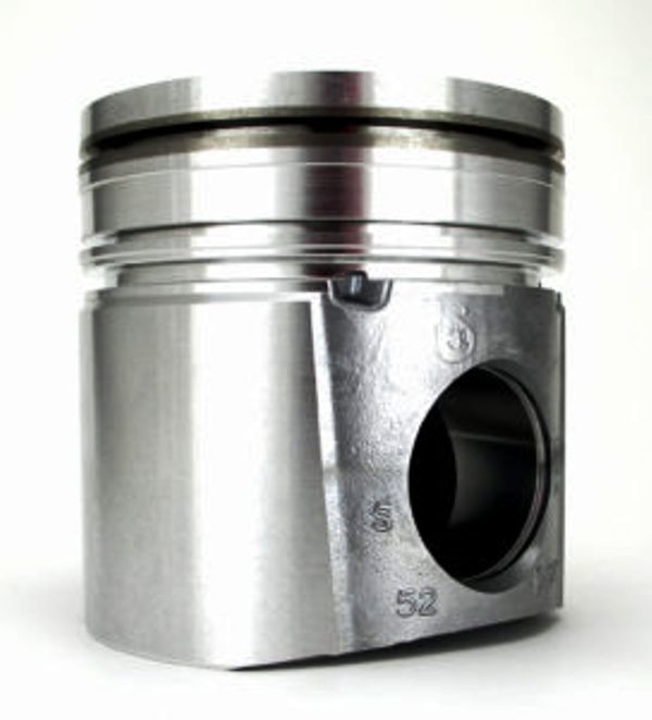
Die casting offers the best dimensional tolerances of any casting process. Fine details and small cavities can be moulded, as well as fine identification lettering. Die casting is characterized by moulding thin-walled parts up to 1.5 mm, surrounded by reinforcing ribs. The surface finish is excellent, and 60 microinches RMS is easily achieved, but 90 microinches RMS is more conservative. Structural parts can be made due to the fine structure caused by rapid cooling, vacuum, and low iron primary alloys. Inserts can also be installed in the mould to change the appearance of the moulding, such as steel.
The technique has several environmental benefits, including the elimination of sand moulds, the ability to use recycled alloys for commercial parts, and the need for minimal post-casting polishing.
Because of the metal’s high pressure, sand cores are not an option. If a metal core (spool) is used in another axis, it must resist the metal’s push, necessitating a more powerful hydraulic system. Consequently, we avoid using cores or a core ejected with the part and removed after the casting. Note the use of salt core for complex cavities, which is then removed by cleaning with water.
Die Casting Markets
In summary, the process offers the following characteristics:
– Minimal cost for large production runs
– Excellent dimensional tolerances and surface finish
– Minimum machining required after casting
– Parts with limited design freedom in 2 axes
– Wide choice of alloys available
The traditional die-casting market is focused on mass-produced parts, small hardware industry, fasteners, housings (covers), and automotive parts (valve covers, wiper arm supports, housings, small engine blocks).
Vacuum processes with structural alloys and semi-solid casting allow structural parts for the automotive market (engine cradles, A and B pillars, door structures, connecting parts).
Die Casting in Australia
Alliance Connect manufactures a comprehensive range of high-quality aluminium die-casting alloys for a variety of applications. They’ve been providing exceptional metal products to all of Australia for over 60 years.