Air conditioning ductwork layouts for multi-storey buildings must reconcile changing cooling loads, limited shaft space and air pressure that shifts with height, temperature and wind. A reliable HVAC system design therefore begins well before duct installation: engineers coordinate the air conditioning layout with the building structure, plan vertical risers and select control zones that suit the spaces they serve. The result should be more than air reaching every floor; it should be consistent comfort, manageable energy use and safe operation throughout the building.
Airflow Challenges in Multi-Storey Buildings
The first design task is understanding how air moves through the entire structure. Warm air naturally rises, creating a stack effect that can draw outdoor air into lower levels and push conditioned air out near the top; wind and seasonal temperature changes can intensify or reverse the pattern.
This vertical pressure gradient affects comfort, energy use and door operation. Designers account for it through coordinated supply, return and exhaust flows, rather than expecting the ducts alone to overcome every imbalance.
Space is another constraint. Shafts must accommodate ducts, piping and other services while preserving structural clearances, fire separation and access for maintenance. A return-air plenum above a ceiling can reduce dedicated duct runs, but its use depends on applicable fire, smoke and material requirements.
Zoning and Pressure Balancing for Reliable Air Distribution
Once building-wide forces are understood, the air conditioning layout can be divided into zones that respond to distinct loads. Exterior rooms gain or lose heat differently from interior spaces, and a sun-facing perimeter may need different control from a shaded one.
Floor-by-Floor Zoning and Exposure
Floor-by-floor zoning is common in buildings with variable air volume (VAV) systems, especially where occupants or operating schedules differ by level. Zones can also reflect orientation, use and internal heat sources, such as a lobby, retail area or equipment room.
This finer control reduces the need to overcool one area to satisfy another. It also gives operators a practical way to respond to changing occupancy without treating the whole building as a single thermal space.
Pressure Balancing and Outdoor Air
Pressure balancing requires supply and exhaust flows to work together. Slight positive pressure is often used to limit unwanted infiltration, while outdoor-air systems, exhaust fans and relief dampers help maintain indoor air quality and respond to changing conditions.
Controls should be commissioned to adjust airflow as needed. If supply and exhaust are poorly matched, occupants may experience drafts or difficult-to-open doors, and contaminants may enter through unintended paths.
Duct Routing, Vertical Risers, and Shaft Coordination
With zoning established, designers can map the path from air-handling equipment to each terminal. Centralized vertical risers can simplify distribution, but their location must be coordinated early with structural elements, corridors and other building services.
Short, direct routes generally limit friction losses and reduce unnecessary bends. Mechanical floors can support decentralized air handlers at intervals in tall buildings, helping avoid excessive pressure demands on a single system; the appropriate arrangement depends on building height, loads and equipment strategy.
The following decisions help translate the concept into a buildable network:
- Calculate heating and cooling loads separately for each floor and zone before sizing ducts.
- Determine zone airflow, then size trunks and branches with suitable velocity and pressure-loss criteria.
- Include filters, coils, dampers, diffusers and fittings when calculating the fan’s required static pressure.
- Reserve access for inspection, cleaning and future maintenance within shafts and mechanical rooms.
These steps establish preliminary dimensions, not a substitute for detailed engineering. The completed design must also account for acoustic performance, equipment selection and the restrictions of the actual building.
Fire Protection, Insulation, and Installation Quality
Ductwork can carry smoke and fire between compartments if penetrations are not protected. Fire and smoke dampers must be selected and installed for the specific rated assembly and application, with access provided for inspection and testing.
Energy requirements also shape the design. Insulation on ducts in unconditioned spaces helps limit unwanted heat transfer and condensation; applicable requirements depend on the project’s location and governing code, such as the IECC or ASHRAE 90.1.
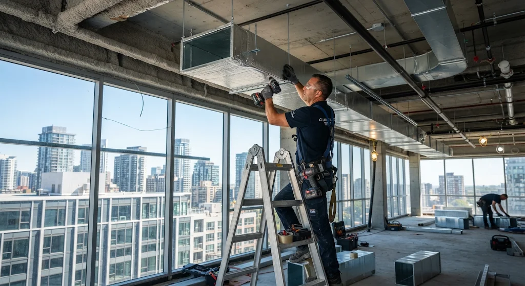
Installation quality determines whether the specified performance is achieved. Sealed joints help prevent leakage, while correctly supported risers preserve alignment and airflow. Service clearances and damper access should remain available after ceilings and finishes are complete.
Commissioning and Performance Verification
After installation, testing, adjusting and balancing (TAB) verifies that measured airflow matches the design. Technicians check terminal flows, set dampers and confirm control sequences, including the interaction between supply, return and exhaust systems.
A useful design review links each system decision to its operational purpose:
| Design Element | Primary Purpose | Verification Focus |
|---|---|---|
| Vertical risers | Distribute air between floors | Access, support and pressure loss |
| Zone controls | Match airflow to varying loads | Setpoints and control response |
| Fire and smoke dampers | Protect compartment boundaries | Correct rating, access and operation |
| Duct insulation and seals | Limit thermal losses and leakage | Continuity and installation quality |
When commissioning confirms the design intent, the system can deliver steadier comfort while supporting safe, efficient operation across floors. For project-specific sizing, code interpretation or troubleshooting, consult a qualified HVAC design professional.